Debugging My Wi-Fi, Part 2: Understanding the System
Before I could figure out what was going wrong, I needed to understand more about my home network: its key components, how they connect, and how data flows between them. This post covers what I learned.
Hardware
When I started my investigation, these were the main pieces of hardware in my home:
- ONT (optical network terminal) - where Verizon’s fiber-optic network enters the house. It converts the optical signal carried over fiber into an Ethernet connection that the router can use.
- Router - Sits between my home network and the internet and forwards traffic between them. The device we call a router is actually several components bundled together: a router, Ethernet switch, Wi-Fi access point, firewall, and services that assign local network addresses. The simple way I think about it is as the main gateway between our devices and the internet at large. Our router is a Verizon CR1000A, which is a tri-band router that supports the 2.4, 5, and 6 GHz Wi-Fi bands (more about bands later!).
- Ethernet port - An Ethernet port is a physical connection found on devices and in the walls of the house. Ethernet cables and ports allow devices to communicate over a wired connection.
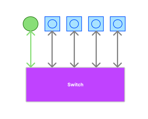
- Ethernet switch - A switch connects multiple wired devices within the same local network and forwards traffic to the appropriate connection. Our switch is a TP-Link five-port switch. In my setup, one port serves as the uplink to the router, leaving four ports for Ethernet runs elsewhere in the house.
WAN and LAN
The router sits at the boundary between two networks:
- The WAN, or wide area network, is the router’s outward-facing connection to Verizon and the public internet.
- The LAN, or local area network, is the private network inside my home. It includes our computers, phones, the Ethernet switch, and any other connected devices.
The ports on the router reflect this distinction. Its WAN port connects to the ONT. Its LAN ports connect to devices inside my home network, either directly or through the Ethernet switch.
How It Is Connected
Here is how this hardware is set up around my home:

The house has four floors, and each major room has an Ethernet port. The router lives in the living room on the second floor. The ONT and five-port Ethernet switch are in the basement.
One Ethernet cable runs from the ONT to the router’s WAN port. A second cable runs from one of the router’s LAN ports back to the Ethernet switch. In this topology, that connection serves as the switch’s uplink. The switch does not have a dedicated uplink port; the term simply describes the port’s role in connecting the switch toward the router. The other four ports connect to Ethernet runs that terminate at wall ports around the house.
Internet traffic from a device connected over Wi-Fi takes this path:
Device
  -> Router (over Wi-Fi)
  -> Router's WAN port
  -> ONT
  -> Verizon
  -> Public internet
Traffic from a wired device passes through one additional component:
Device
  -> Wall port
  -> Ethernet switch
  -> Router's LAN port
  -> Router's WAN port
  -> ONT
  -> Verizon
  -> Public internet
Here is a simplified view of the switch. The router’s LAN connection occupies one port, leaving four ports for wired connections elsewhere in the house:
Key concepts
Knowing the physical path was only half the problem. To capture an intermittent failure, I also needed to record where each device was connected, what the wireless link looked like, and whether packets were moving reliably.
Identifying a Wi-Fi connection
- Service Set Identifier (SSID) - the network name displayed when you select a Wi-Fi network on your device. When you go to select the wifi you want to on your device, the name of the network that is listed is the SSID .Access points announce their networks using beacon frames.
- Basic Service Set Identifier (BSSID) - the identifier, usually formatted like a MAC address, for one specific Wi-Fi connection offered by an access point. A single access point can have several BSSIDs, such as one for each band or network name. Multiple access points can broadcast the same SSID while exposing different BSSIDs. This lets me determine which particular connection a device was using when a problem occurred.
- Repeater (or extender) - a device that extends a Wi-Fi network’s coverage. It connects wirelessly to the router or another access point, then receives and retransmits network traffic in an area where the original signal may be weak. Its placement matters: it must be close enough to receive a reliable signal while still reaching the area that needs better coverage.
- Access point - a device that provides Wi-Fi connectivity to a wired network. Unlike a repeater, it usually connects to the router or network switch over Ethernet, so it does not depend on another wireless connection to carry traffic. Most home routers include a built-in access point, but additional ones can be installed to improve coverage.
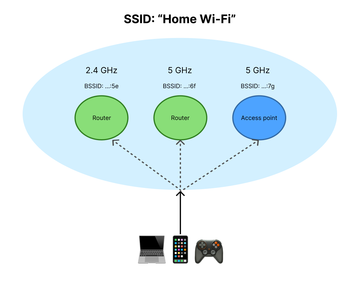
Together, the SSID, BSSID, and band tell me not merely that a device was “on Wi-Fi,” but which wireless connection it was using.
Understanding the Wireless Link
- Band - a range of radio frequencies used for Wi-Fi communication. Today’s Wi-Fi networks commonly use the 2.4, 5, and 6 GHz bands. Lower frequencies generally travel farther and pass through walls more effectively, while higher frequencies generally offer more capacity but have a shorter effective range. A device usually chooses which available band and access point to use, sometimes with guidance from the network.
A router that supports two bands is commonly called dual-band. Tri-band means it operates three Wi-Fi radios, but those may use 2.4, 5, and 6 GHz or one 2.4 GHz radio and two 5 GHz radios.
- 2.4 GHz - generally provides the longest range but has less capacity and is often more congested. It works well for devices that need coverage more than high throughput.
- 5 GHz - generally provides a balance of range and capacity. It is commonly used by laptops, phones, and streaming devices.
- 6 GHz - provides additional, less-congested spectrum and supports wide channels, but generally has the shortest range and requires compatible devices.
- Channel - a portion of a Wi-Fi band that an access point and its connected devices use to communicate. Nearby networks using the same channel must share airtime. Partially overlapping channels can also interfere with one another, particularly in the crowded 2.4 GHz band. Channel width affects how much spectrum a connection occupies. The 5 and 6 GHz bands have room for more channels than the 2.4 GHz band.
- Signal - the strength of the access point’s radio transmission as received by a connected device. It is commonly measured in dBm and represented as a negative number, such as -65 dBm. A value closer to 0 indicates a stronger signal. If interested in signal, dBm, etc. here’s a good post about it.
- Noise - unwanted radio energy detected by a device alongside the desired Wi-Fi signal. It can come from electronics and wireless devices operating on nearby frequencies and can make the signal harder to interpret. Like signal, noise is measured in dBm, but a value farther from 0 indicates less noise.
- Signal-to-noise ratio (SNR) - the difference between the strength of the Wi-Fi signal and the background noise. It is calculated by subtracting noise from signal and is measured in dB. For example, a signal of -50 dBm and noise of -90 dBm produce an SNR of 40 dB. A higher SNR is better.
These values describe the wireless environment, but no single one proves that the connection is healthy. A strong signal can still perform poorly on a busy channel, which is why I will need to compare them with measurements of actual network performance.
Measuring performance
- Throughput - the rate at which data is successfully transferred, usually measured in Mbps, or megabits per second. Throughput is the speed I actually observe, which may be lower than the connection’s advertised or theoretical maximum speed.
- Latency - the delay between sending data and its arrival, usually measured in milliseconds. It can be measured in one direction, but tools such as
pingtypically report round-trip time: how long a request takes to reach a destination and return. - Jitter - variation in latency across a series of packet transfers, usually measured in milliseconds. There are several ways to calculate it, so any measurement is only meaningful if I know which method the tool uses. Regardless of the calculation, high jitter means packets are not arriving at consistent intervals, which can cause problems for video calls and other real-time applications.
- Packet loss - the percentage of transmitted packets that never reach the expected destination. Data sent over a network is divided into packets, and lost packets may have to be retransmitted or may cause visible interruptions. Ideally, packet loss should be as close to zero as possible.
Now that we have a good understanding of the key components and concepts, we can now start to monitor some of these and build up a data set that will allow us to hypothesize what is going wrong. We will discuss this in the next part of this series: Probing.